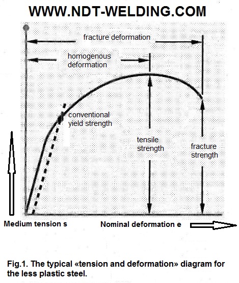
At less plastic metals the differences in the characteristics which are obtained in areas of elastic deformation and plastic deformation can be not so noticeable. Therefore, to determine the yield point it is hardly possible to use the «Drop of the Beam» method. The method which is called the «Offset» method gives other opportunities. The dependence curve between tension and deformation is typical for the less plastic metals and is shown in Fig. 1.
Applying the «Offset» method, we draw the line beginning at the point with a given deformation value and parallel to the curve, which determines the modulus of elasticity. The deformation size is usually expressed as a percentage. The typical offset is about 0.2% (0.002) of the deformation value and also different values can be set. The creation of the displaced line at the offset value 0.2% can be seen in Fig. 2.
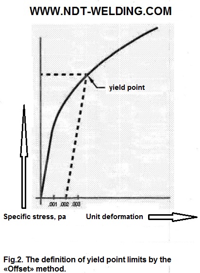
As the yield point is accepted the voltage value at the intersection point of the displaced line «tension – deformation». This value must be entered in the reporting documentation as the yield point at offset 0.2%, as those who studies the test results, it is necessary to know the conditions in which the yield point value was defined.
After the actual test work is necessary to define the metal ductility. This parameter can be shown in two ways: as the extension and as the reduction of area. Both methods assume carrying out the measurements before and after the test.
To determine the relative extension per sample it is necessary to write on marks limiting the gauge length of the sample, and then applying a load thereto. After the sample destruction, samples’ two parts are joined together and measure the new distance between the calculated marks. When you are aware of the starting and ending calculated distance between two marks, the relative extension can be calculated as follows:
Start working length of the sample = 2.0 inches.
End working length of the sample = 2.6 inches.
Relative extension = ((end length) – (start length)/start length)*100.
Relative extension = ((2.6-2.0)/2.0)*100 = 30%.
The ductility can be expressed through the local contraction of metal section during the tensile test. Such value is called the relative contraction, and the start and end cross-sectional areas of the tensile sample are defined by means of measurements and calculations, the results of which are compared. The procedure for this calculation is given below:
Start area = 0.2 square inches.
End area = 0.1 square inches.
Relative contraction = ((start area) – (end area)/start area)*100.
Relative contraction = ((0.2-0.1)/0.2)*100 = 50%.


